sales@powerlinecomponents.com
International: 1-307-885-4724
US (Toll Free): 877-885-4724
Back to Detroit Diesel Engine Information
Series Inline 53 Model Description Chart Application, Rotation and Design Variations
| 5 | 0 4 | 3 | - | 5 | 1 | 0 0 |
| Series 53 |
# Of Cylinders |
Application Designation (see below) |
Basic Engine Arrangement (see below) |
Design Variation (see below) |
Specific Model # |
- 5042 - 5100 Marine
- 5043 - 5100 Fan to F/W Industrial
- 5044 - 5100 Power Base
- 5045 - 5100 Generator
- 5043 - 5000 "N" Engine
- 5043 - 5100 2 Valve Head
- 5043 - 5200 4 Valve Head
- 5043 - 5300 Turbocharged
Specific Model #
If Last Digit is an Odd Number, Starter Is Located Opposite of Blower.
If Last Digit is an Even #, Starter is Located Same Side of Blower.
2, 3 & 4-53 Basic Engine Arrangements
Rotation: R (right) & L (left) designates rotation as viewed from the front of the engine.
Type: A-B-C-D designates location of exhaust manifold & blower as viewed from the flywheel end of the engine.
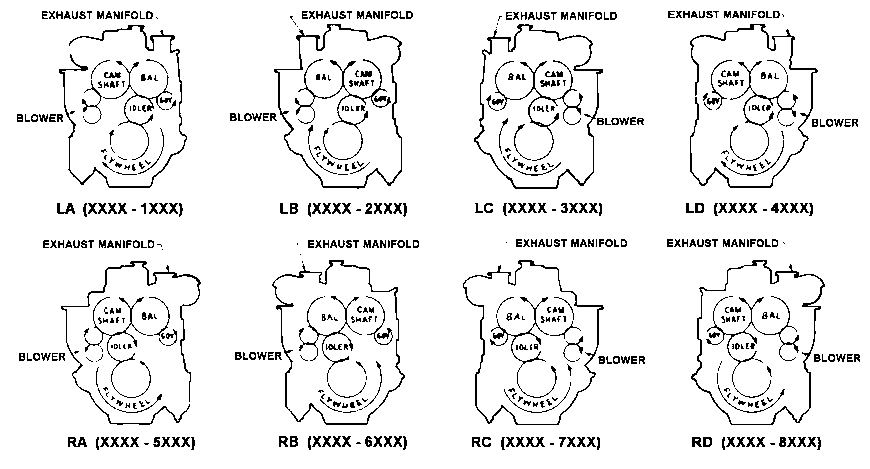
ALL VIEWS FROM REAR (FLYWHEEL) END OF ENGINE
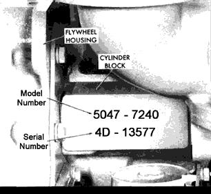
On the in-line engines, the model # & serial # are stamped on the right-hand side of the cylinder block in the upper rear corner.
An example of a Series 4-53 serial # is 04DXXXXXXX. Engines built in Brazil have a serial # prefix of 3DB (three cylinder), & 4DB (four cylinder). The engine serial # is required when placing a parts order.
Model # 5043-5100 is interpreted as follows: Series 53 Engine (5), four cylinder (04), industrial, fan to flywheel (3), right-hand rotation with "A" accessory arrangement (5), two-valve head engine (1), & specific model # 00 (00).